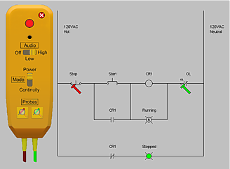
When the power is on in our new "Troubleshooting Mode", power flow isn't shown and only some symbols show when they receive power (Motors, lights, horn, coils and other loads). Also only some symbols can be pressed or activated (Switches, Pushbuttons, Circuit Breakers). Since components can be made defective, just because you click on a N.O. pushbutton doesn't mean power is flowing through it when it looks like it is closed.
It's as close as we can make it to troubleshooting a real circuit using a ladder diagram format. Be sure to check out our Troubleshooting Mode video.
The Troubleshooting mode is like a midway point between a printed ladder diagram and a real control circuit. It can be used to train students how to find problems in electrical circuits (blown fuses, bad pushbuttons or switches, open or shorted motors or coils, broken wire, etc.) with a test probe and print reading skills.
Our test probe is used to test for power or continuity.
How it Works for the Instructor:
1. First you create a working ladder diagram
2. Then you decide what components you want to make defective and then modify the diagram.
3. Add any notes or comments to the workbook or notes section.
4. Change to the Troubleshooting mode and Save the diagram.
Now when a student opens the diagram they will be in our Troubleshooting mode.
How it Works for the Student:
1. Open the diagram
2. Then read any comments in the workbook section.
3. Turn the power on.
4. Now try the circuit and find out what's not working correctly.
5. Troubleshoot the circuit with the test probe
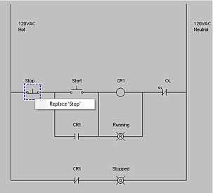
6. Once you find a problem, turn the power off, hover over the bad the component or wire and select "Replace"
7. Turn the power back on and check if the circuit works or test and see if more components are bad and need replacing.
We have 4 sample troubleshooting diagrams with the program (in the "Troubleshooting Sample Ladder Diagrams" folder), that should help get you going with this new mode. Each samples name includes the number of defects in the diagram.
Using the Test Probe
To use the Test Probe click the main breaker, left click the probe icon on the toolbar if the probe is not visible. Drag the probe (Left click and hold) to the location you prefer.
Set the probe mode to Power or Continuity.
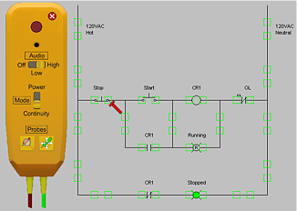
Click on the Red Lead Icon on the probe and move the lead to a location indicated by the red squares shown on the circuit. Do the same for the Green Lead.
To move a lead just click on it and move to a new location. To put a lead back on the probe click on the lead and click your keyboard ESC key.
Power or continuity will be indicated by the red light on the probe and an audio tone if the audio on your probe and computer is turned on.